Unified Modeling Language (UML) is a standardized general-purpose modeling language in the field of object-oriented software engineering. The standard is managed, and was created, by the Object Management Group. It was first added to the list of OMG adopted technologies in 1997, and has since become the industry standard for modeling software-intensive systems.[1]
UML includes a set of graphic notation techniques to create visual models of object-oriented software-intensive systems.
Overview
The Unified Modeling Language (UML) is used to specify, visualize, modify, construct and document the artifacts of an object-oriented software-intensive system under development.[2] UML offers a standard way to visualize a system's architectural blueprints, including elements such as:- activities
- actors
- business processes
- database schemas
- (logical) components
- programming language statements
- reusable software components.[3]
UML models may be automatically transformed to other representations (e.g. Java) by means of QVT-like transformation languages. UML is extensible, with two mechanisms for customization: profiles and stereotypes.
Software development methods
UML is not a development method by itself;[11] however, it was designed to be compatible with the leading object-oriented software development methods of its time (for example OMT, Booch method, Objectory). Since UML has evolved, some of these methods have been recast to take advantage of the new notations (for example OMT), and new methods have been created based on UML, such as IBM Rational Unified Process (RUP). Others include Abstraction Method and Dynamic Systems Development Method.[edit] Modeling
It is important to distinguish between the UML model and the set of diagrams of a system. A diagram is a partial graphic representation of a system's model. The model also contains documentation that drives the model elements and diagrams (such as written use cases).UML diagrams represent two different views of a system model:[12]
- Static (or structural) view: emphasizes the static structure of the system using objects, attributes, operations and relationships. The structural view includes class diagrams and composite structure diagrams.
- Dynamic (or behavioral) view: emphasizes the dynamic behavior of the system by showing collaborations among objects and changes to the internal states of objects. This view includes sequence diagrams, activity diagrams and state machine diagrams.
[edit] Diagrams overview
UML 2.2 has 14 types of diagrams divided into two categories.[13] Seven diagram types represent structural information, and the other seven represent general types of behavior, including four that represent different aspects of interactions. These diagrams can be categorized hierarchically as shown in the following class diagram:
In keeping with the tradition of engineering drawings,[citation needed] a comment or note explaining usage, constraint, or intent is allowed in a UML diagram.
Structure diagrams
Structure diagrams emphasize the things that must be present in the system being modeled. Since structure diagrams represent the structure, they are used extensively in documenting the software architecture of software systems.- Class diagram: describes the structure of a system by showing the system's classes, their attributes, and the relationships among the classes.
- Component diagram: describes how a software system is split up into components and shows the dependencies among these components.
- Composite structure diagram: describes the internal structure of a class and the collaborations that this structure makes possible.
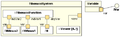
- Deployment diagram: describes the hardware used in system implementations and the execution environments and artifacts deployed on the hardware.
- Object diagram: shows a complete or partial view of the structure of an example modeled system at a specific time.
- Package diagram: describes how a system is split up into logical groupings by showing the dependencies among these groupings.
- Profile diagram: operates at the metamodel level to show stereotypes as classes with the <<stereotype>> stereotype, and profiles as packages with the <<profile>> stereotype. The extension relation (solid line with closed, filled arrowhead) indicates what metamodel element a given stereotype is extending.
-
 Class diagram
 -
 Component diagram
 -
 Composite structure diagrams
 -
 Deployment diagram
 -
 Object diagram
 -
 Package diagram


[edit] Behaviour diagrams
Behaviour diagrams emphasize what must happen in the system being modelled. Since behaviour diagrams illustrate the behavior of a system, they are used extensively to describe the functionality of software systems.- Activity diagram: describes the business and operational step-by-step workflows of components in a system. An activity diagram shows the overall flow of control.
- UML state machine diagram: describes the states and state transitions of the system.
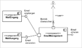
- Use case diagram: describes the functionality provided by a system in terms of actors, their goals represented as use cases, and any dependencies among those use cases.
-
 State Machine diagram


[edit] Interaction diagrams
Interaction diagrams, a subset of behaviour diagrams, emphasize the flow of control and data among the things in the system being modeled:- Communication diagram: shows the interactions between objects or parts in terms of sequenced messages. They represent a combination of information taken from Class, Sequence, and Use Case Diagrams describing both the static structure and dynamic behavior of a system.
- Interaction overview diagram: provides an overview in which the nodes represent communication diagrams.
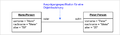
- Sequence diagram: shows how objects communicate with each other in terms of a sequence of messages. Also indicates the lifespans of objects relative to those messages.
- Timing diagrams: a specific type of interaction diagram where the focus is on timing constraints.


[edit] Meta modeling

Beyond the M3-model, the Meta-Object Facility describes the means to create and manipulate models and metamodels by defining CORBA interfaces that describe those operations. Because of the similarities between the Meta-Object Facility M0-model and UML structure models, Meta-Object Facility metamodels are usually modeled as UML class diagrams. A supporting standard of the Meta-Object Facility is XMI, which defines an XML-based exchange format for models on the M3-, M2-, or M1-Layer.
No comments:
Post a Comment